
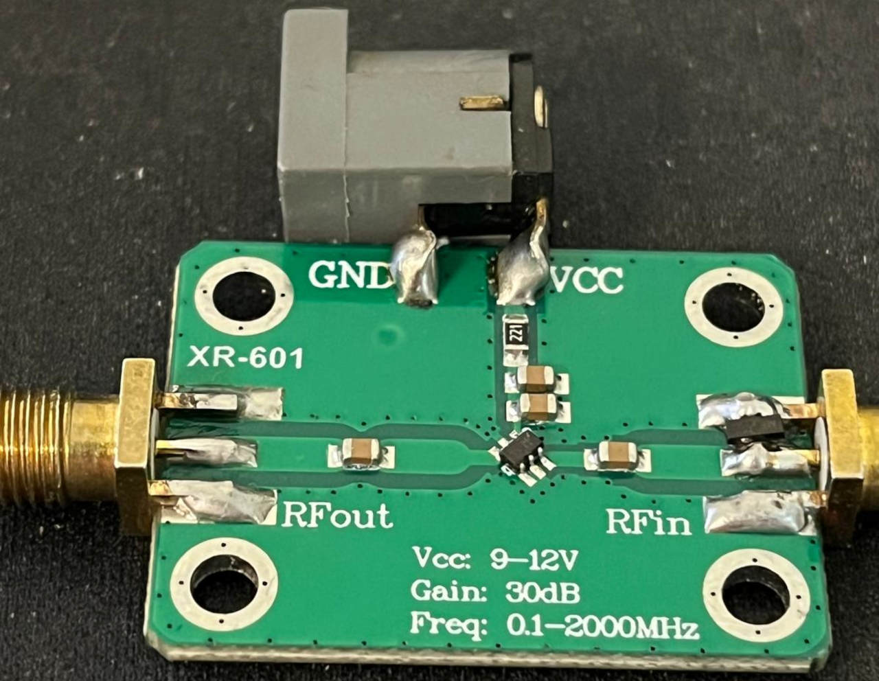
The XR-601 is a cheap Chinese SMA amplifier board that claims 30 dB of gain from 0.1 to 2000 MHz. I tested one with a POP SDR MSI NANO receiver and a wire antenna to see what it does in practice. It boosts weak signals as advertised, but the noise floor rises with them, and the power circuit is cruder than I expected.
The hardware
The XR-601 is a bare board with an SMA connector at each end, an RF amplifier IC, a handful of capacitors, and one resistor in the power circuit. There is no shield can and no voltage regulator.
The markings give these specifications:
- Frequency range: 0.1–2000 MHz
- Gain: 30 dB
- Supply voltage: 9–12 V
These are the manufacturer’s claims. I didn’t verify them independently.
I made two changes before testing. I soldered a DC power connector to the board so I could run it from a bench supply, and I added a small low-capacitance protection diode at the RF input as a guard against static discharge coming in through the antenna. That isn’t lightning protection, and I haven’t surge-tested it. It’s a cheap precaution when you’re experimenting with improvised antennas.
Test setup
I used about one meter of wire as the antenna and tuned the SDR to an FM broadcast station at 103.5 MHz. Location, equipment, antenna and SDR settings were identical for both runs, and I took the readings a few minutes apart. The only change was putting the XR-601 between the antenna and the receiver.
Results
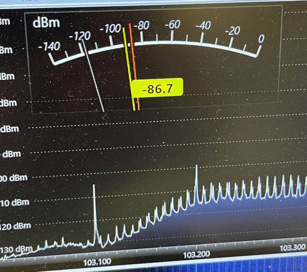
Without the amplifier, the SDR showed a signal level of about −86.7 dBm. The station was receivable but weak, and the spectrum display showed a fairly low noise floor with a few neighboring signals.
With the amplifier powered up, the level rose to about −59.2 dBm, a gain of 27.5 dB. The audio was audibly clearer and louder, so this wasn’t just a number on the meter.
A caveat: these are SDR software readings, not calibrated RF measurements. Receiver gain behavior, impedance matching and calibration all affect the absolute figures. Still, in this setup the amplifier clearly raised the received signal level by a large margin.
The noise problem
The signal went up, and so did the noise floor. The difference was obvious on the spectrum display. Without the amplifier the background was low. With the XR-601 connected, the whole trace lifted and many more peaks stood out.
That doesn’t mean all of the extra noise comes from the amplifier. An LNA amplifies everything at its input, including antenna noise, interference, and weak signals that were previously buried below the receiver’s floor, and it adds some noise of its own. Strong signals can also overload an amplifier or receiver and create spurious products.
Pinning down the cause would take proper measurements: signal-to-noise ratio, noise figure, and intermodulation performance. What I can say is that the station sounded better while the spectrum looked a lot busier. More gain doesn’t automatically mean better reception.
The power circuit
The board appears to drop the supply voltage with a single series resistor rather than a regulator. With 12.3 V at the connector, I measured about 5.96 V at the amplifier IC, a drop of 6.34 V. The resistor is marked 121, which means 120 Ω. If the whole drop is across that resistor, the estimates are:
- Current: about 52.8 mA
- Power dissipated in the resistor: about 0.335 W
These are calculated values. I didn’t measure the current or the voltage across the resistor directly.
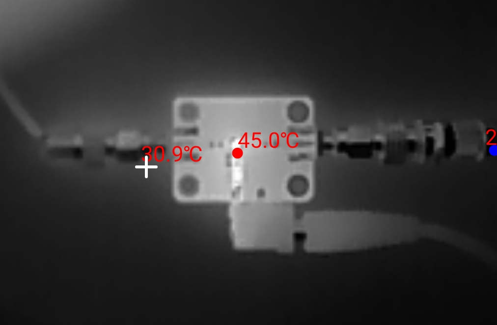
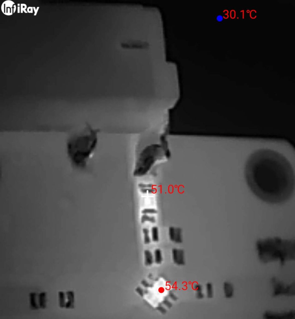
An InfiRay thermal camera showed the board running warm:
- About 51.0°C near the power resistor
- About 54.3°C near the amplifier IC
- About 45°C in the center of the board
- About 30.1°C at a cooler reference point in the scene
Those temperatures are not alarming and are probably within the components’ ratings. Thermal camera readings can be skewed by emissivity, reflections and small component size. But the board clearly wastes a fair amount of power as heat.
A series resistor is also not a regulator. The voltage at the IC depends on the current it draws, so it will shift with supply voltage and operating conditions. I’d like to look into how stable the module really is across its 9–12 V range.
Impedance matching
Amplifiers like this are designed for 50 Ω systems, but real antennas rarely cooperate. A one-meter wire at 103.5 MHz is nowhere near a matched 50 Ω antenna, and it still produced a useful improvement. That’s not surprising, since a mismatch doesn’t stop an amplifier working, especially for receive-only use. The real questions are how much performance you lose and whether a matching network would help.
For reference, connecting a 75 Ω antenna to a 50 Ω input produces a theoretical mismatch loss of only about 0.18 dB, assuming purely resistive impedances. Other antennas are harder. A tuned magnetic loop can present a very different feed impedance depending on how it’s coupled and what frequency you’re on. Small untuned broadband loops are usually meant to work with specialized low-input-impedance amplifiers, not a generic 50 Ω LNA, so plugging one into an XR-601 may disappoint. I plan to cover that in a separate article.
Should you buy it?
For experimenting, it’s a worthwhile little board. It delivered 27.5 dB more signal in my test and made a weak FM station noticeably easier to listen to.
I wouldn’t pick it for a serious low-noise receive chain. The elevated noise floor needs more investigation, the power arrangement is crude, and there’s no shielding. An external amplifier can also make things worse if your receiver already struggles with strong local signals. For serious SDR work, gain is only one factor alongside noise figure, linearity, filtering and antenna matching.
Bottom line
In this test, the XR-601 increased the SDR’s indicated signal level by 27.5 dB, close to its advertised 30 dB gain. With a one-meter wire at 103.5 MHz, the SDR’s displayed signal rose by 27.5 dB and the audio improved. It also raised the displayed noise floor considerably, and its resistor-based power circuit pushed component temperatures past 50°C.
That makes it neither good nor bad, just a cheap module that’s useful if you understand its limits. I’m keeping it as an experimental tool, not a universal upgrade for reception.
If you’ve measured the XR-601’s noise figure or linearity, or tried matching it to a magnetic loop, I’d like to hear about it in the comments.